
When you first unroll a set of architectural drawings, it can look pretty intimidating—a sea of lines, symbols, and notes. But once you know the language, it all starts to click. The key is to break it down into a few fundamental pieces: the title block, the scale, the symbols, and the main drawing types like floor plans, elevations, and sections. Getting a handle on these is your foundation for reading any blueprint like a pro.
Your First Look at a Set of Blueprints

It’s easy to feel lost when you’re staring at a full set of construction documents. They look more like a complex puzzle than a building guide. But don’t worry, there’s a system to it, and every set of drawings is organized with a clear, logical structure. You just need to know where to begin.
Your starting point should always be the title block. You’ll almost always find it in the bottom-right corner of every single sheet. I like to think of it as the drawing’s ID card; it holds all the critical project information you need before you even look at the design itself.
What to Look for in the Title Block
Before you dive into the lines and dimensions, make a habit of scanning the title block first. It grounds you in the project and gives you the context for everything else on the page. Skipping this simple step is a rookie mistake that can cause a lot of headaches later.
Here’s the essential information you’ll find there:
- Project Name and Location: Tells you exactly what building you’re looking at and where it is.
- Architect/Designer Information: Shows who is responsible for the design—the firm, the architect, and their contact details.
- Sheet Title and Number: This is crucial. It tells you what the drawing depicts (“First Floor Electrical Plan,” for example) and its page number in the full set (like A-101).
- Revision History: A log of any changes made to this specific drawing. It includes dates and brief descriptions of the updates.
I can’t stress this enough: always check the revision history. Projects evolve, and drawings get updated. Working from an old sheet is a recipe for expensive mistakes. Make sure you have the most recent version before you do anything else.
Getting familiar with this information first frames the entire project for you. You’ll know who designed it, what specific part of the building you’re examining, and whether the information is current. This initial orientation is a fundamental part of the overall architectural design process steps and sets you up to interpret the rest of the drawings with confidence.
Decoding the Language of Lines and Symbols
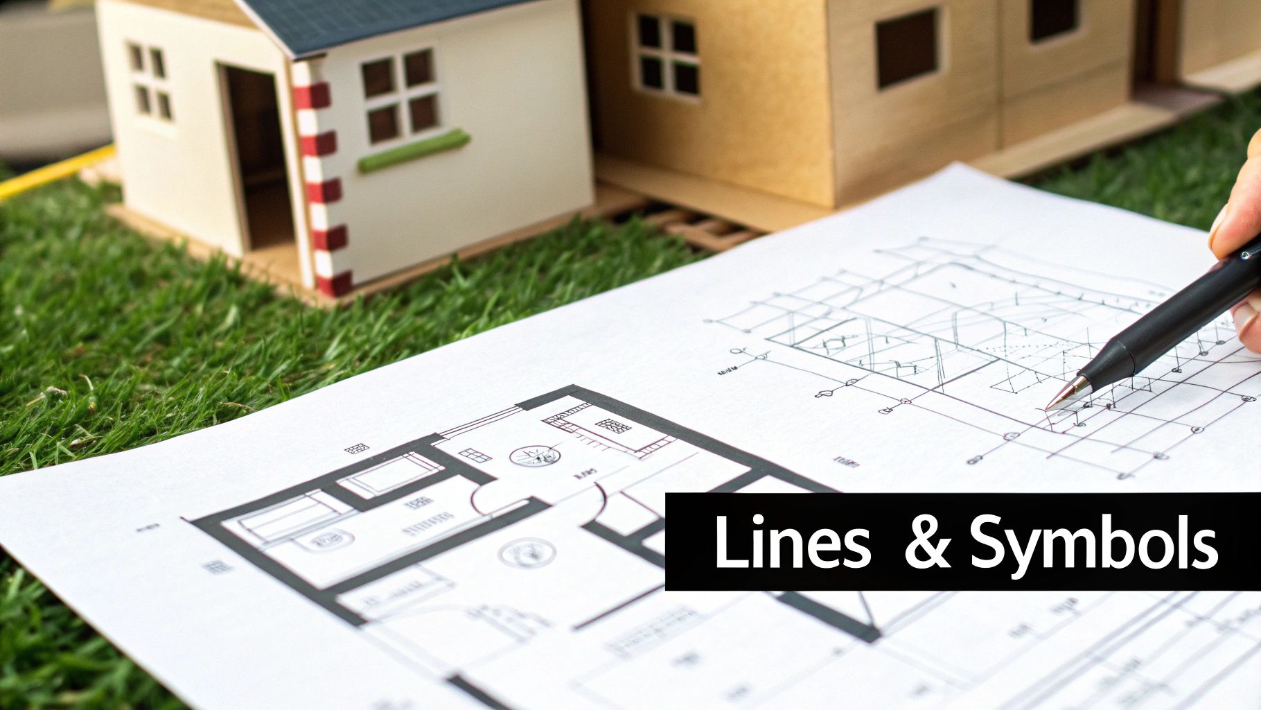
Think of architectural drawings as a visual language. They have their own vocabulary and grammar, and the lines and symbols are the words that tell the story of a building. To read these drawings fluently, you have to learn this language first. It’s the only way to grasp what the architect is trying to communicate with absolute clarity.
Every single line on a plan has a specific job, which you can tell by its weight (how thick it is) and its style (solid, dashed, or something else). This isn’t just about making the drawing look nice; it’s a code. A thick, solid line is almost always telling you that you’re looking at a major structural piece, like a load-bearing wall, that’s been sliced through for that particular view.
On the other hand, a much thinner solid line might show something that isn’t structural at all, like a built-in bookshelf or a kitchen countertop. Then you have dashed or dotted lines, which represent things you can’t see from that vantage point—maybe a beam in the ceiling above, the outline of the roof, or even a utility line buried underground.
Understanding Common Line Types
The first thing I always look at is the hierarchy of the lines. Before you even try to decipher a single symbol, get a feel for what the lines are saying about the building’s bones.
- Thick Solid Lines: These are the big players. They almost always represent walls and other key structural components.
- Thin Solid Lines: These fill in the details—things like furniture, fixtures, and surface finishes that aren’t holding the building up.
- Dashed Lines: This is the architect’s way of saying, “There’s something important here, but it’s hidden.” It could be an element above or below the current floor plan.
- Center Lines: You’ll see these as a long-short-long pattern. They mark the exact center of an object or feature, which is crucial for getting alignments just right.
Here’s a pro tip I always share: Think of line weight as a sign of importance. The heavier the line, the more critical that element is to the building’s structure. It’s a visual cue that naturally guides your eye to what matters most on a potentially crowded drawing.
Translating Common Architectural Symbols
Once you’ve got a handle on the lines, it’s time to look at the symbols. Drawings are filled with standardized icons that represent everything from a door to an electrical outlet. While any good set of drawings will include a legend that defines them all, learning to spot the common ones instantly will make your life a whole lot easier.
A classic example is a door. It’s shown as a straight line sitting in the wall, with a quarter-circle arc showing the direction it swings open. That little arc is surprisingly important—it tells you everything about the room’s flow and where you can (and can’t) place furniture. A window usually looks like a break in the wall, filled with a few thin parallel lines to represent the glass and frame.
The way we use these symbols has changed dramatically with technology. Before the 1980s, everything was drawn by hand. Now, digital drawings make up over 98% of plans produced, with CAD software cutting drafting time by as much as 70%. This digital shift has packed more information than ever into our drawings, making symbol recognition an essential skill. You can discover more insights about how digital tools have reshaped design.
When you know the symbols, you can start to see how a space will actually function. Spotting the icons for a sink, toilet, and shower tells you you’re looking at a bathroom. On an electrical plan, you’ll see symbols for outlets, switches, and light fixtures scattered around, showing you exactly how the space gets its power and light.
Translating Scale and Dimensions into Reality
The lines and symbols on a drawing are just abstract art until you apply scale. Scale is what transforms a simple diagram into a precise, buildable instruction manual. It’s the foundational rule that dictates how every measurement on the page corresponds to its actual size in the real world.
Without a clear grasp of scale, you’re just looking at a picture, not a blueprint. This translation from paper to reality is what makes architectural drawings so powerful—it ensures a line that’s just a few inches on paper becomes a full-sized, correctly placed wall on a construction site. Mastering this concept is absolutely essential.
Understanding Common Architectural Scales
Architects use standardized scales to maintain consistency and clarity across all their drawings. You’ll almost always find the scale noted in the title block or somewhere directly on the drawing itself. The scale used often depends on how much detail is needed.
- Imperial Scales (common in the U.S.): You’ll constantly see scales like 1/4″ = 1′-0″. This simply means every quarter-inch on the drawing represents one full foot in reality. It’s a go-to scale for residential floor plans because it offers a good balance of detail and overall view.
- Metric Scales (common internationally): Ratios like 1:50 or 1:100 are the standard. A 1:50 scale means one unit of measurement on the drawing is equal to fifty of the same units in real life. So, one centimeter on paper would be fifty centimeters (or half a meter) on the ground.
Using standardized scales isn’t a new idea. This practice really took hold during the Renaissance, and by the 17th century, a whopping 90% of surviving European architectural plans were using a consistent scale. This historical shift was what paved the way for the precise, universally understood plans we rely on today. If you’re curious about the backstory, you can discover more insights about the history of architectural drawings.
My biggest piece of advice is to invest in an architect’s scale ruler. It’s a triangular ruler with multiple scales printed on its sides. It does the conversion work for you, eliminating guesswork and preventing the costly errors that come from miscalculations.
To help you get a feel for which scales are used for which purposes, here’s a quick breakdown of the most common ones you’ll encounter.
Common Architectural Scales and Their Uses
| Scale (Imperial) | Scale (Metric) | Typical Use |
|---|---|---|
| 1/16″ = 1′-0″ | 1:200 | Site plans and large-scale overviews where minute detail isn’t the priority. |
| 1/8″ = 1′-0″ | 1:100 | Standard for overall building plans and elevations. |
| 1/4″ = 1′-0″ | 1:50 | Very common for residential and commercial floor plans. A good balance of detail. |
| 1/2″ = 1′-0″ | 1:20 | Enlarged plans for specific areas like kitchens, bathrooms, or stairwells. |
| 1″ = 1′-0″ | 1:10 | Detailed drawings of specific components like cabinetry or complex joints. |
| 3″ = 1′-0″ | 1:5 | Highly detailed section drawings or construction details. |
Knowing these will help you immediately understand the context and level of detail you’re looking at when you first open a drawing.
Reading Dimension Strings
While you can measure things with a scale ruler, architects provide exact measurements through dimension strings. These are the lines with numbers on them running parallel to walls and other features, telling you their precise length and location.
A dimension string has a few key parts:
- Extension Lines: Thin lines that extend from the object being measured.
- Dimension Line: The line running between the extension lines, with the actual measurement written on it.
- Tick Marks or Arrows: These show exactly where the dimension line begins and ends.
You’ll often see multiple strings of dimensions stacked together. The outermost string usually gives the overall dimension of a building or a large section. As you move closer to the building, the inner strings break that overall dimension down into smaller, more specific measurements—like the distances between windows, doors, and wall corners.
Always, always trust the written dimensions over any measurement you take yourself with a scale ruler. The printed numbers are the “source of truth.” A critical part of any good interior design space planning guide is cross-referencing these dimensions to ensure everything fits perfectly. For example, check that the overall wall length on the outer string matches the sum of the smaller dimensions on the inner strings. If they don’t add up, it’s a big red flag that there’s an error in the drawing that needs to be addressed immediately.
Visualizing the Building in 3D From 2D Plans
Architectural drawings are, in essence, a clever illusion. They use a series of flat, two-dimensional views to describe something incredibly complex and three-dimensional. The real trick to reading them isn’t just knowing what the symbols mean—it’s training your brain to mentally stitch these separate views together into a complete picture.
Think of it like assembling a puzzle. Each piece—the floor plan, the elevations, the sections—reveals a different angle. Only when you put them all together does the final image of the building emerge. The first step is getting comfortable with what each of these core views is designed to show you.
Starting with the Floor Plan: The Bird’s-Eye View
For most people, the floor plan is the most familiar and intuitive place to start. It’s your foundational map. Imagine slicing the building horizontally, about four feet off the ground, and looking straight down. That’s a floor plan.
This “bird’s-eye view” is your master guide to the layout, the flow, and how different spaces relate to one another on a single level.
With a floor plan, you can immediately grasp:
- The layout of rooms, hallways, and other spaces.
- Where doors and windows are located and how big they are.
- The thickness and material of the walls.
- The placement of key fixtures like stairs, sinks, or kitchen appliances.
The floor plan is the anchor for all the other drawings. You’ll constantly see symbols on it that refer to other views, like a line indicating where a section is cut or an arrow showing the direction of an elevation view. Everything comes back to the plan.
Moving to Elevations: The Exterior Perspective
Once you’ve got a handle on the internal layout, it’s time to see what the building looks like from the outside. That’s the job of the elevation drawings.
An elevation is a perfectly flat, 2D drawing of one of the building’s exterior faces. A complete set usually gives you four views: North, South, East, and West. They don’t show depth like a photo would; instead, their purpose is to provide hard facts about the vertical surfaces.
Elevations will tell you the building’s overall height, the roof’s shape and pitch, and what materials are used on the exterior walls (like brick, siding, or stucco). You’ll see the precise placement of windows and doors on each side, which you can then match up with their locations on the floor plan.
The ability to create realistic views was a major turning point in architecture. Before the 14th century, drawings were mostly flat and two-dimensional. Today, over 95% of architectural firms use perspective views in presentations because they offer a more natural understanding of a design. You can learn more about the history of architectural sketching to explore this evolution.
This infographic shows a simple three-step process for using a scale to translate drawing measurements into real-world dimensions.
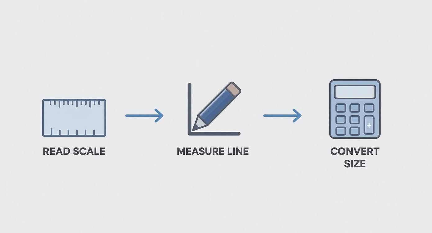
This visual guide simplifies the process of reading scale, moving from identifying the correct scale to measuring a line and finally converting it to its actual size.
Uncovering the Interior with Section Drawings
If elevations show you the outside, section drawings slice the building open to reveal what’s going on inside its bones. Think of it like cutting a layer cake in half to see all the fillings. A section is a vertical slice taken right through the structure.
This view is invaluable for understanding how a building is actually put together.
The “cut line” for any section is always marked on the floor plan, usually with a bold line and arrows pointing in the direction of the view. Looking at the section drawing itself, you’ll see details hidden in every other view:
- The foundation and footing details below ground.
- The construction of the floors, walls, and roof assembly.
- The heights of ceilings and the space between floors.
- The profile of a staircase as it rises from one level to the next.
The real magic happens when you start connecting these views. Find a window on the front elevation. Now, find that same window on the floor plan to see which room it’s in. Finally, hunt down a section that cuts through that window—there you’ll see its height from the floor and how it’s framed into the wall.
Practicing this kind of cross-referencing is what builds that powerful 3D model in your mind, turning flat lines on a page into a space you can almost walk through.
Practical Tips and Common Mistakes to Avoid
Moving from theory to practice is where the real learning begins. You can understand what a floor plan or an elevation is, but fluently reading a full set of construction documents is a different skill entirely. It’s all about developing a systematic approach and knowing the common pitfalls that can trip up even experienced pros.
When a fresh set of plans hits my desk, I have a go-to method: start big, then drill down. I’ll always begin with the site plan to get my bearings—how the building sits on the property, its orientation, and its relationship to its surroundings. From there, I move to the overall floor plans to grasp the layout, then to elevations and sections. Only then do I dive into the nitty-gritty details for specific areas like kitchens or stairwells. This top-down approach keeps me from getting lost in the weeds before I see the whole forest.
Adopting a Proactive Review Workflow
A consistent review process is your best defense against costly mistakes. The first thing I do is grab a few different colored highlighters. It might sound simple, but it’s a game-changer for tracing complex systems across multiple pages.
- Trace the Systems: I’ll use one color to follow the plumbing lines from a fixture on the floor plan all the way to the main stacks shown in the section drawings. Another color might be for tracing critical HVAC ductwork. This visual map makes it incredibly easy to spot potential conflicts, like a drainpipe clashing with a structural beam.
- Always Check Revisions: Before you do anything else, find the title block and look for the revision schedule. It’s been shown that nearly 22% of all construction rework comes from using bad project information. Working from an outdated drawing is a recipe for disaster, so make sure you have the latest version. It’s non-negotiable.
- Read All the Notes: It’s so easy to focus on the lines and symbols, but the notes contain the real meat. Critical specifications, materials, and installation details live in those little text blocks. Overlooking a single keynote could mean ordering the wrong windows or completely missing a crucial waterproofing detail.
My number one rule is to never assume anything. If a dimension looks strange or a detail isn’t clear, flag it right away. A five-minute question for the architect upfront is infinitely cheaper than a five-day fix on-site.
Common Mistakes That Lead to Rework
Knowing what not to do is just as important as knowing what to do. I’ve seen beginners and seasoned professionals fall into the same traps time and again. The most common error? Misreading the scale.
Someone will glance at a drawing, assume it’s the standard 1/4″ = 1′-0″, and start taking measurements for materials. Later, they realize it was actually drawn at 1/8″ = 1′-0″, and their entire takeoff is wrong. This simple mistake can throw off material orders, screw up layouts, and create massive headaches.
Another classic blunder is failing to cross-reference information between different drawings. You might look at a window on an elevation and think it looks great. But if you don’t check it against the floor plan and the section view, you could miss that it directly conflicts with a structural column. A building is a three-dimensional object, and you have to check all the 2D views together to catch these clashes before they become expensive, built-in problems.
Common Questions About Reading Blueprints
As you get the hang of reading blueprints, you’ll find certain questions come up again and again. It’s totally normal. Tackling these common sticking points is the best way to build your confidence and make sure you’re catching every important detail.
One of the first hurdles for many is understanding the different types of drawings. What’s the real difference between architectural, structural, and MEP plans?
Think of it like this:
- Architectural Drawings: This is the vision. They show the layout, the look, and the feel of the space—everything from room dimensions and window placements to finish materials and door types.
- Structural Drawings: This is the building’s skeleton. These plans detail the foundation, the steel beams, the load-bearing walls, and everything else that holds the structure up safely.
- MEP Drawings: This is the central nervous system. MEP stands for Mechanical, Electrical, and Plumbing. These sheets show you where the HVAC systems run, how the electrical wiring is laid out, and where every pipe and fixture is located.
Each set is usually handled by a different specialist, but they all have to work together perfectly. A good project manager knows you have to overlay them (even just mentally) to spot potential clashes before they become real-world problems.
Clarifying Key Distinctions
A question I hear all the time is, “What do I trust more—the drawing or the notes?” The answer is simple and non-negotiable: always trust the written specifications and dimensions over any measurement you take with a scale ruler.
Drawings can get distorted when they’re copied or scanned. A line might look like it’s ten feet long, but the printed dimension is the legally binding truth.
It’s a mantra on every job site: the numbers rule. If a dimension string says a wall is 10′-2″, but your ruler says it’s 10′-0″, you build a 10′-2″ wall. End of story.
People also wonder what happens after the architect hands over the plans. Their job isn’t done. The drawings are the primary communication tool, but most architects stay involved during construction, ensuring the builder is following the plans to the letter. If you’re starting a project, knowing how to find an architect who will see it through construction is one of the smartest decisions you can make.
So, what happens if you spot a mistake? Maybe the dimensions on one wall don’t add up, or you see a plumbing line running straight through a concrete beam. It happens more often than you’d think.
The professional move is to immediately stop and submit a Request for Information (RFI). This is a formal query sent to the architect or engineer asking for an official clarification. It’s how you solve problems on paper before they become costly, time-consuming fixes on-site.
At Haute Design, we connect you with premier architects and designers who create flawless plans and bring extraordinary visions to life. Explore our network to find the right professional for your next project. Find Your Designer on hauteliving.com/designnetwork.